Width determination of steel strips in the rolling process – radar systems for industrial applications


Conventional measurement systems are frequently not able to cope with the harsh environmental conditions in hot rolling mills. For this reason, Fraunhofer FHR and IMS Messsysteme GmbH have, for the first time, developed a precise width measurement system based on radar technology. One great advantage of this system is the fact that is can be used even in the most adverse conditions.
Harsh environmental conditions and high demands
Quality and efficiency in the production of rolled products are very closely linked to the development and usability of measurement techniques for tracking and regulating the rolling process. Improvements to existing measurement techniques increase productivity and reduce production costs. The width of the steel strip is a fundamental parameter in the rolling process. Due to the presence of dirt or steam, conventional measurement systems can not be used or can only be used with great difficulty to take a width measurement at the roughing stand, one of the essential width regulation steps in the rolling process. Parallel to this, the requirements placed on the sensors, even under these conditions, are very high. Apart from precise measurement, requirements include high reliability in 24/7 operation, temperature stability over a range of -10°C to 55°C, robustness against vibrations as well as fast and easy integration into existing systems.
In the past, regulation was carried out on the basis of theoretical models and empirical values. However, errors that occur at this point cannot be corrected in the course of rolling process as the width can no longer be influenced in later processing stages. To guarantee that the target width is achieved over the entire length of the strip, the strip is rolled wider than required and the surplus width is removed at the end of the rolling process. Over the course of a year, this excess width produces several thousand tons of steel scrap which has to be melted down again. This not only requires additional resources such as energy, material, personnel and machine hours but also results in the production of several tons of CO2 per year. Moreover, each millimeter of excess width reduces the length of the strip and hence, the overall output.
Fraunhofer FHR, in cooperation with IMS Messsysteme GmbH, has developed a radar-based width measurement system to close this gap in process control. Two frequency modulated continuous wave radars independently measure the distance to the steel strip that is passing the radar beam. For this purpose, they are installed opposite each other on either side of the rolling path. Calibration then takes place to correlate the two measurements so that the width and the center position of the strip can be determined on the basis of the range measurements.
From the laboratory to the steel mill
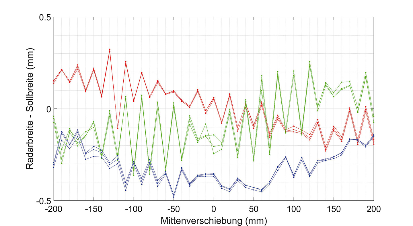
The radar systems were tested in the testing facilities of IMS Messsysteme GmbH. In line with the planned installation scenario at the rolling path, two radar systems were installed opposite each other at a distance of 5 m. A positioning unit, which moves various test and calibration bodies along the axis between the two radar units, is located between the two systems. The encoder of the positioning unit, which is certified for ±60 µm, is used to control the individual distance measurements. The certified test bodies with typical widths that occur at the roughing stand serve to monitor the measurement accuracy of the width measurement system as a whole. The required measurement accuracy at the roughing stand of ± 1 mm was easily achieved with a deviation below ± 0.5 mm for all widths. Fig. 2 shows the difference between the measured and the certified width value.
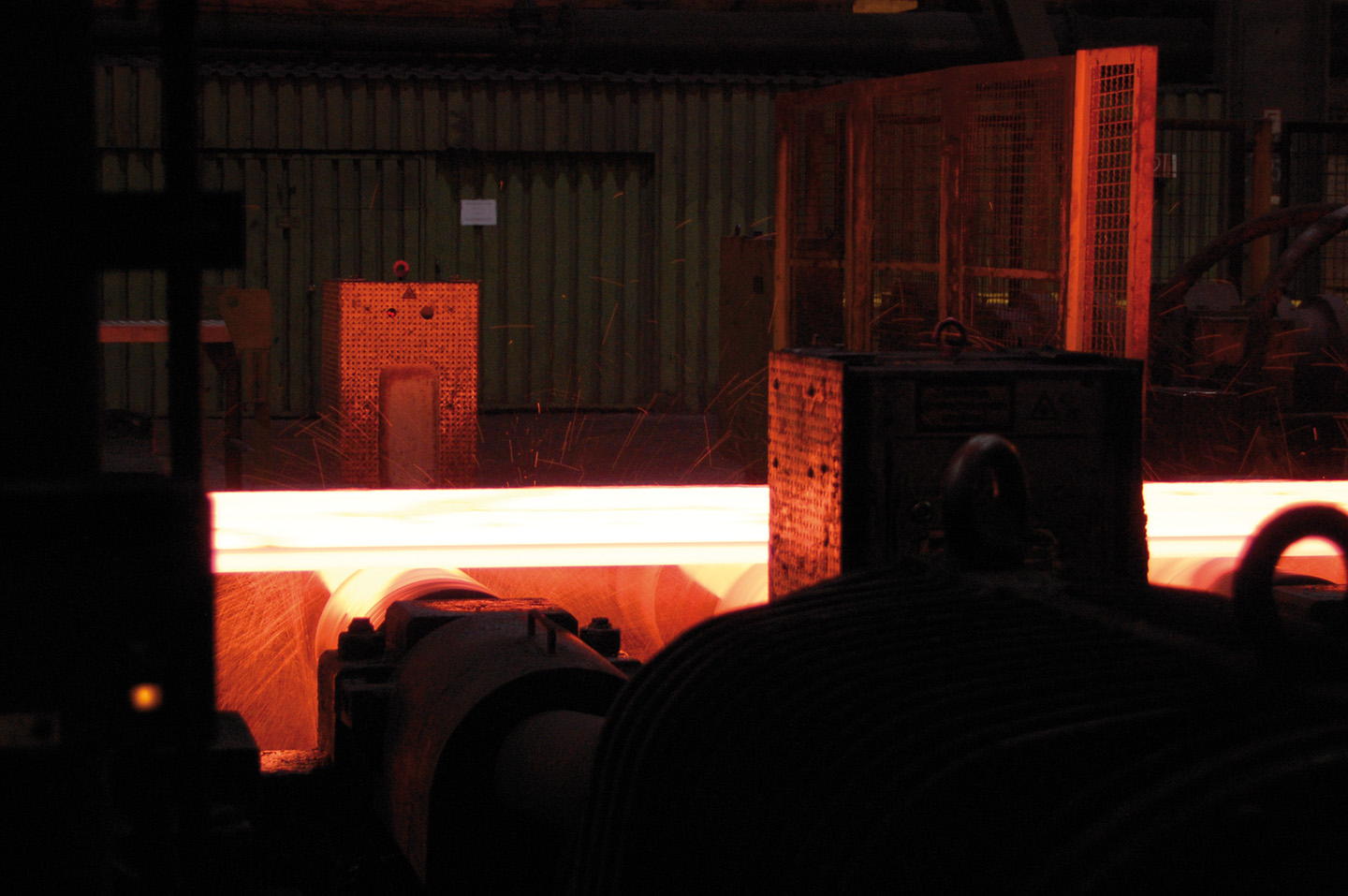
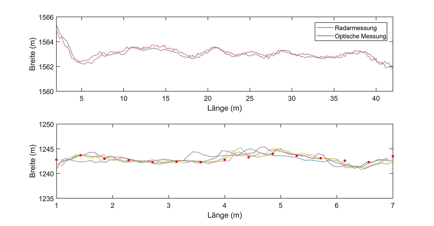
The radar-based width measurement system was installed and tested at the roughing stand in the hot strip mill of Salzgitter Flachstahl GmbH. Due to the small size of the sensor system and the independence of the individual sensors, the size of the installation can be adapted to the respective measuring sites. Fig. 1 shows the installed width measurement system at the roughing stand at Salzgitter Flachstahl GmbH. Steel strip with widths of between 800 mm and 2050 mm and thicknesses of between 50 mm and 250 mm are rolled here. An optical width measurement system of IMS Messsysteme GmbH is located behind the roughing stand at the entrance of the production line. Fig 3 shows an example of the width profile of a steel strip which was measured by the radar-based width measurement system and the optical measurement system. The width profiles of both systems show a high level of agreement. The radar width measurement is not influenced by the very harsh conditions at the roughing stand.
To further test measurement accuracy, a piece of strip with a length of 7 meters was cut out of the input strip, placed on the rolling path and once again measured and tested by the radar measurement system. The results are shown in Fig. 3. There was a high level of agreement between the radar measurement and the manual measurement. The radar measurement also displayed high repeatability.
For the first time, the obstacles to precise width measurement in hot strip mills were overcome with radar technology. At the beginning of 2017, a fully industrialized version of the radar-based width measurement system was installed and commissioned in Salzgitter. Since then, the radar width measurement system has been measuring the width of steel strips reliably, precisely and trouble-free in 24/7 operation. In addition to the advantages described above, the system parameters of the measurement system can be adapted individually with the result that radar measurement is also very attractive for other application areas.